
Introduction
Please Note: iParts4U are currently running training days at our HQ. Although you can attempt to use this guide without formal training, we do highly recommend booking a training day with us. If you’d like to book a training day, get in touch at [email protected] for more information.
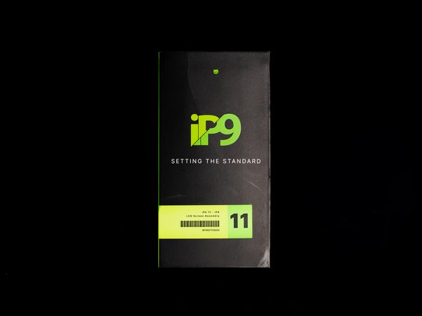
In this guide we’ll be transferring an original iPhone 11 IC onto a new IP9 display. We're doing this in order to transfer the original display serial data over to the new display which will in turn remove the 'Non-Genuine' display message that appears once an aftermarket display is fitted to an iPhone.
To transfer serial data across to an aftermarket display we would usually have to solder the original IC onto the same location on the new display, see our guide here on how to do so. We're happy to be the first to offer a new technology that allows you to solder the original IC onto the display flex with a dramatically lower chance of damaging the screen in the process. This is possible due to an added section of the flex that you can solder the original IC to.
Out of the box, the IP9 display still comes with an IC chip which is located in its usual position and contains all of the usual features to enable the display to function such as true tone & display touch.
You might be wondering why this is an important advancement and there's a couple of reasons why this new technology is beneficial:
1. The number one reason is safety & assurance, running a repair business can be challenging, especially if you do happen to make a mistake. Small errors can cost you valuable time and money, having the added flex means that even if you were to damage the flex during the IC swap, you’d still have a fully functioning display (with the exception of the 'non-gen' battery message being removed). This is especially important as most suppliers do not cover damage to the flex, so if you were to swap the IC via the traditional route, you risk being left with a screen that does not function.
2. There is less of a risk of damaging the polorizer due to the location of the flex. This is a common error with swapping IC’s as you’re working over the polarizer, the new placement takes away this risk due to its placement.
We’re aware that some repairers are hesitant to learn and invest in microsoldering, however we believe Apple screen repairs could become a serious issue for repairers if software compatibility issues continue limiting replacement screens from functioning to their true potential, which is why we believe that micro soldering is an important skill for all repairers to learn and hopefully this new technology will help repairers take the leap into micro soldering.
It's worth noting that you'll still need to programme the IC for true tone regardless of whether you fit the original IC or not.
All of the tools we used in this guide are linked below so be sure to check them out!
Tools
- Thermal Polyimide High Temperature Kapton insulation Tape - 20mm x 35m
- QianLi Portable iUV Intelligent Curing Lamp
- X-Acto Knife Blade - No.11 - 10 Pack
- Mechanic RoHS Lead-Free Solder Paste - 138°C - V4B45 - 40g
- 2UUL Desktop Fume Extractor With Filter
- QianLi Chip Remover / Cleaner - 009
- Aixun T3B-210 Intelligent Soldering Station Kit
- Mijing HY258 SMT Solder Flux 10cc
- Cotton Swabs Of Dust Cloth For Cleaning x 100
- Chemtronics 80-4-5 Desoldering Wick - 1.5m
- 2UUL PCB UV Green Curable Soldering Mask - 10cc
- 2UUL Welding Wire - 183 Degrees - 100m x 0.3mm - 50g
- Atten ST-862D High Power Hot Air Station
-
-
Before starting this repair we recommend fully discharging your battery to reduce the risk of a short when re-connecting your new display.
-
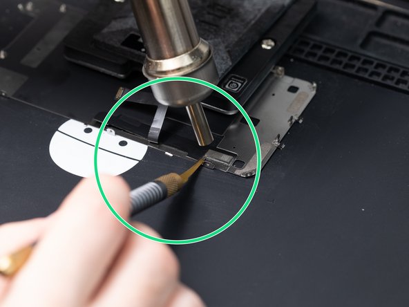
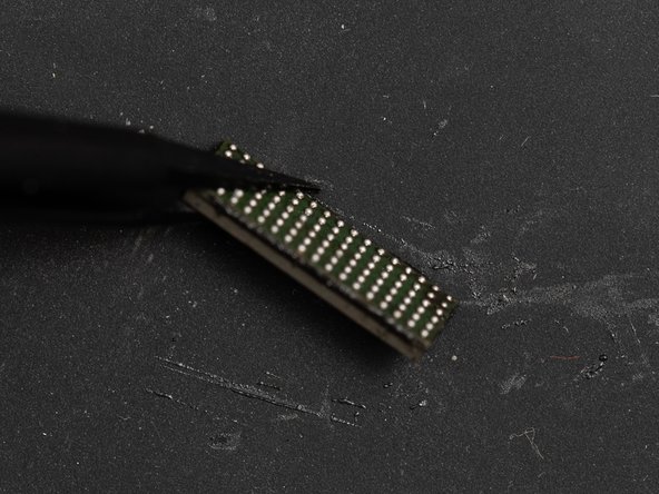
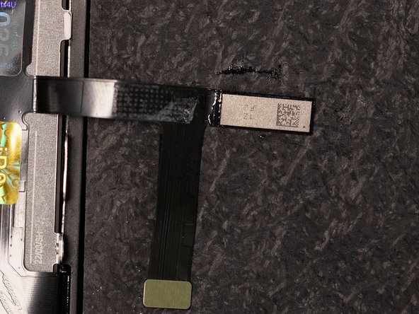
To start this tutorial you'll need an iPhone 11 LCD back plate with the original IC and flex cable connected. You'll need to separate the back plate and flex from the original display assembly.
-
We use a blade to cut the flex on the back plate.
-
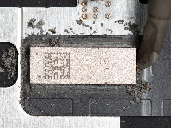
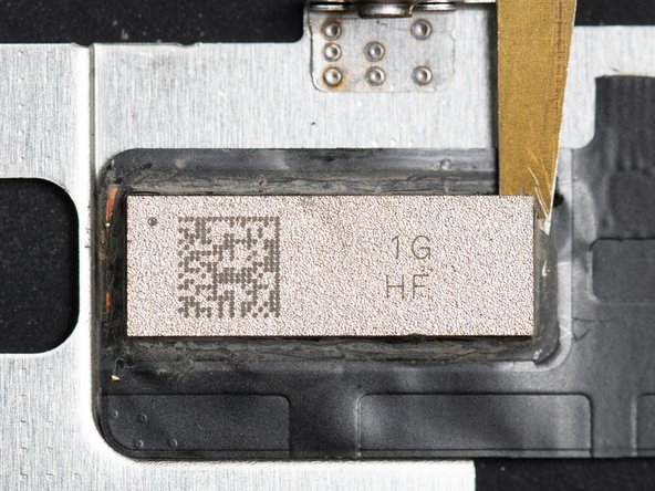
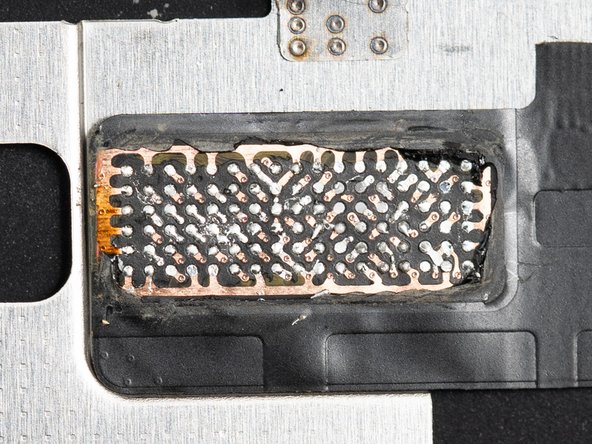
On the back plate you'll find the IC Chip at the end of the touch flex.
-
-
-
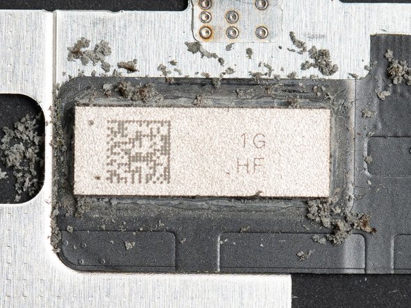
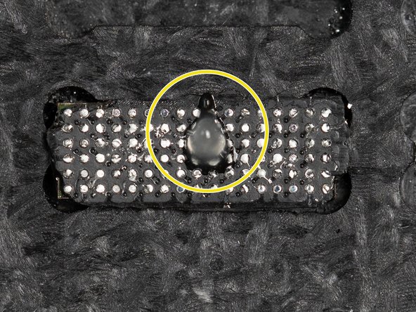
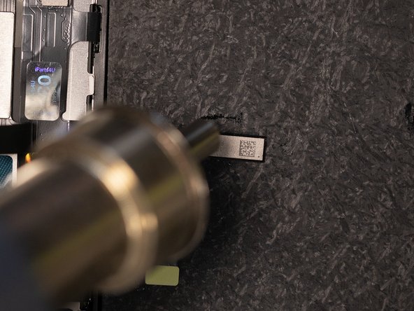
In order to remove and transfer the IC chip you'll need to remove the underfill glue holding it down. The glue is the thin black line surrounding the chip.
-
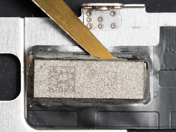
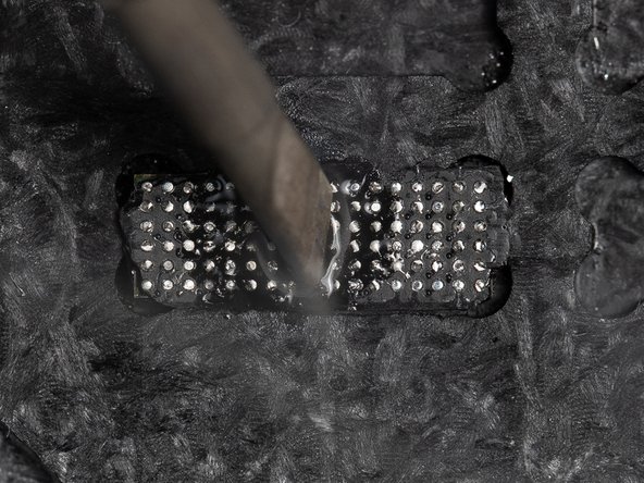
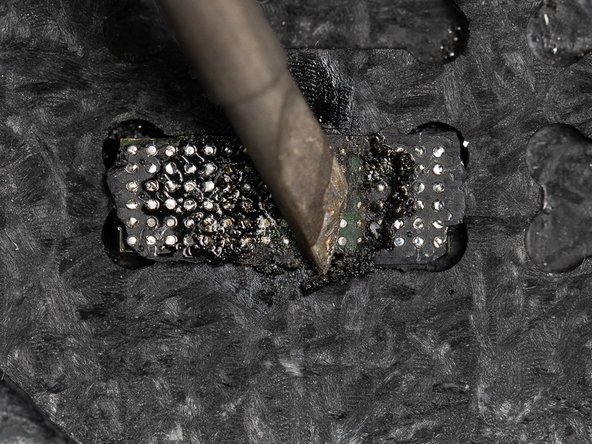
Using the tip of your soldering iron at 400°C start cleaning the underfill glue around the IC chip using a back and forth motion. Start in the middle and work on creating an opening, once the opening is created continue scraping left to right.
-
As you move your soldering iron back and forth you should notice the glue crumbling and residue will begin appearing around the chip.
-
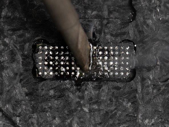
When removing the glue with the soldering iron it's important to be careful not to apply too much pressure as this can cause issues later when removing the chip. Also be conscious that you need to keep the soldering iron moving regularly, as keeping it stagnant in one spot could cause the chip to overheat.
-
-
-
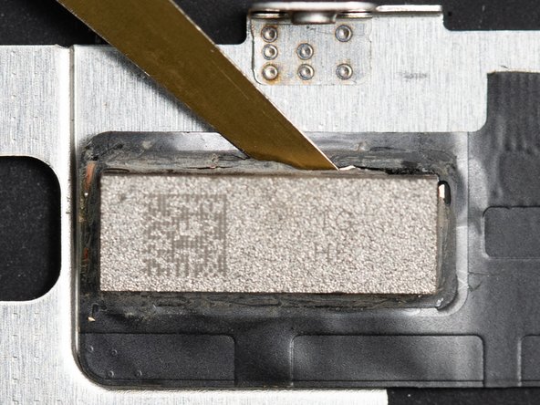
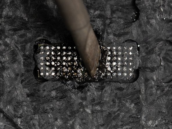
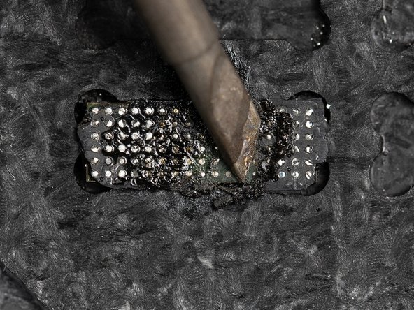
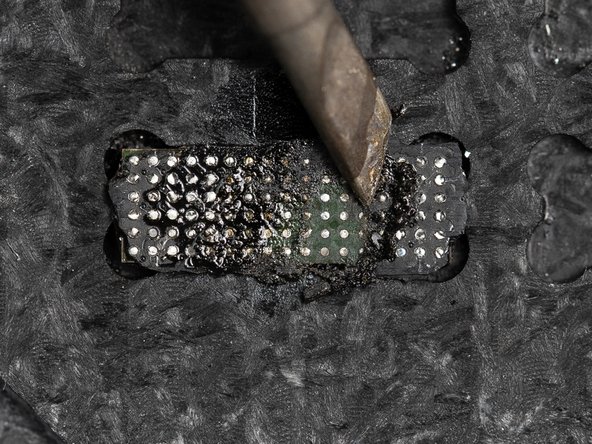
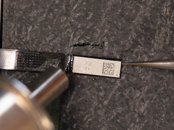
Continue cleaning all four corners of the chip until all of the glue has been removed.
-
You should aim to clean one of the four corners extra thoroughly as you'll be prying from one specific corner in future steps.
-
-
-
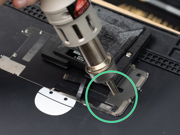
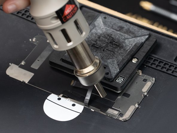
Using a hot air station at 400°C with the airflow set to 100, heat the IC by circling it with your hot air nozzle.
-
Temperatures may vary depending on what solder rework station you're using.
-
Heat around the IC for up to 5 seconds.
-
We're using a circular motion to avoid overheating the chip. In the next step we'll be heating the IC more consistently.
-
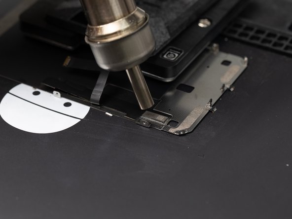
We're holding the hot air nozzle around 5cm away from the chip. Skip to the next step to help gauge how far away we're holding the nozzle from the chip.
-
-
-
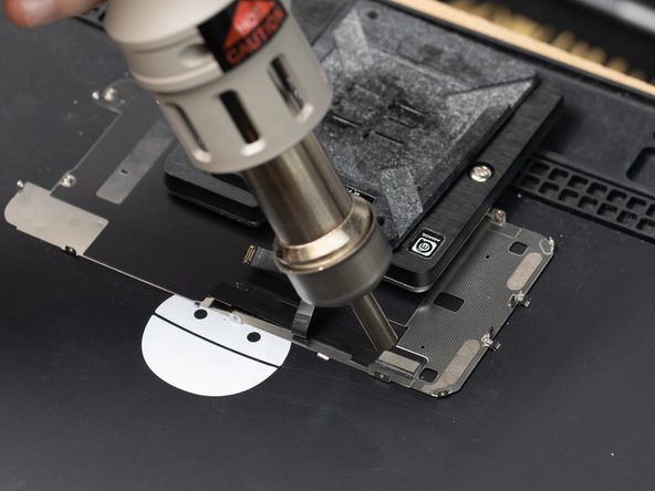
Hold the nozzle 5cm away from the chip and continue the circular motions discussed in Step 4.
-
-
-
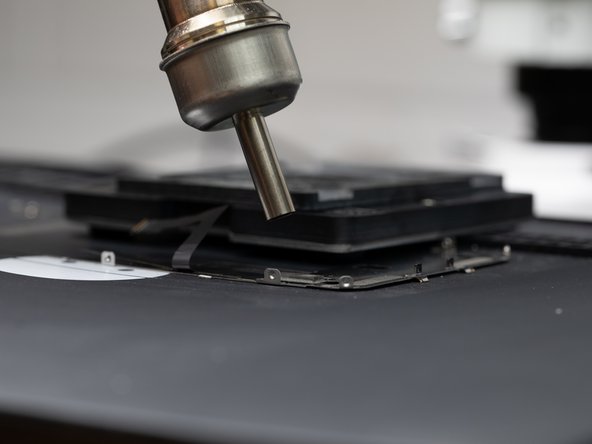
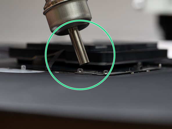
Adjust your heating distance to bring your heat gun in to around 1-2cm away from the chip.
-
Instead of using a circular motion with the nozzle, bring your heat gun to the centre of the chip and hold it there for consistent heat.
-
Skip to the next step to begin prying.
-
-
-
Now the chip is hot we can start prying it off. Use a Qianli chip remover tool or something similar to begin prying the chip up.
-
Starting in one of the corners, sweep the remover tool back and forth against the corner of the chip until an opening is created.
-
You should continue heating the chip with your hot air nozzle so the chip doesn't cool down while you're prying.
-
Be careful not to overheat the chip by holding the nozzle over the chip for too long.
-
You may notice air bubbles coming out from the sides of the chip, this is an indication that you're close to overheating the chip. If you do see the air bubbles, don't panic, this is fairly common, just move the hot air further away from the chip to allow it to cool.
-
-
-
Once you've managed to create an opening at one of the corners of the chip you'll need to continue prying at an angle underneath the entire chip.
-
The best motion for prying the IC off is a side to side motion with your qianli cleaner tool.
-
Continue this side to side motion underneath the entire chip to free it from the underfill glue.
-
Be careful as you pry the final section of the chip, the chip may fling off.
-
-
-
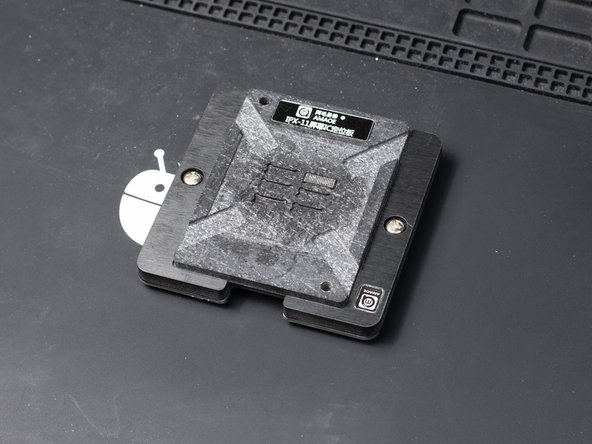
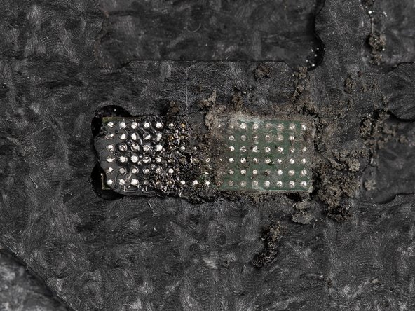
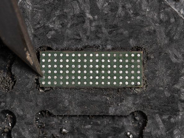
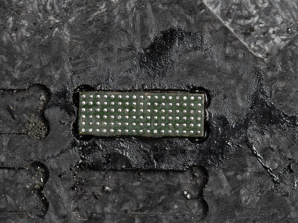
Place your iPhone 11 IC Chip into an iPhone 11 reballing platform.
-
We're doing this so we can remove the remaining underfill glue from the bottom of the chip.
-
-
-
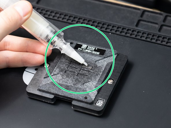
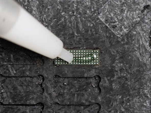
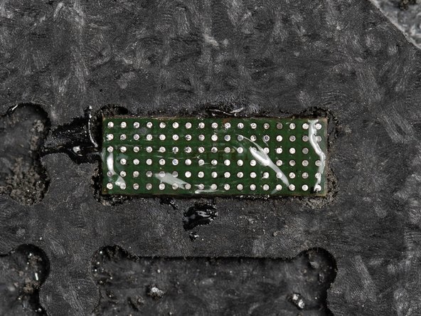
With your chip firmly resting inside the reballing platform, apply solder flux to the back of the chip.
-
You'll only need a small drop, aim for enough to cover the chip with a thin coating.
-
The solder flux will help us remove the glue with a soldering iron in the next few steps. The flux helps melt the solder and speed up the process.
-
-
-
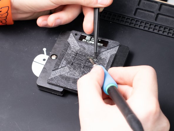
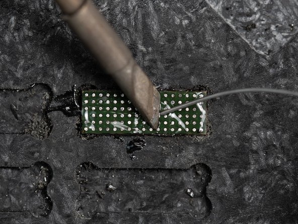
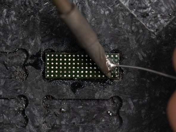
Set your soldering iron to 400°C and place it in the centre of the IC chip.
-
This will create fumes, use a fume extractor to avoid any negative health consequences due to fume exposure.
-
Start firmly scraping the solder iron against the chip. This will start melting the underfill glue and you'll see the glue come away from the chip.
-
Be careful not to hold the solder iron in one spot for too long, you run the risk of damaging or overheating the chip if you aren't moving the solder iron regularly. Skip to the next step to see how to properly move your soldering tip.
-
From time to time take your soldering tip off of the chip to give it a chance to cool down.
-
-
-
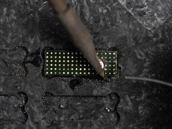
The most efficient way of removing the underfill is with the soldering iron on a slant and rubbing it in an up & down motion.
-
-
-
When moving out towards the edges of the IC, use tweezers to hold the chip in place so it doesn't pop out of the reballing platform.
-
It's best to work your way out to one of the edges of the chip slowly.
-
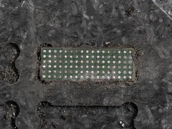
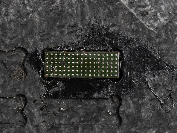
As you continue removing the underfill you'll start seeing the green layer underneath.
-
-
-
Once you've finished removing the underfill on one side, switch to the next side and remove all of the underfill.
-
-
-
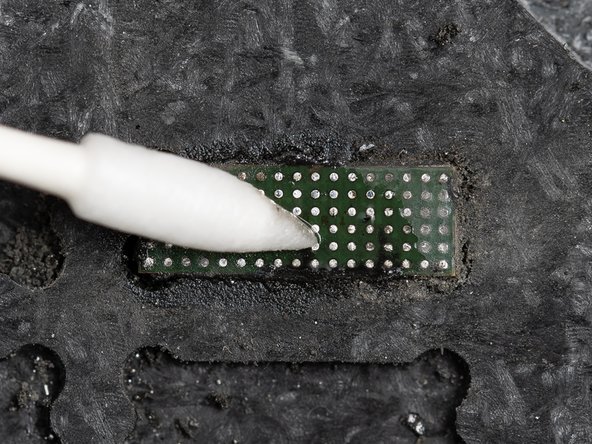
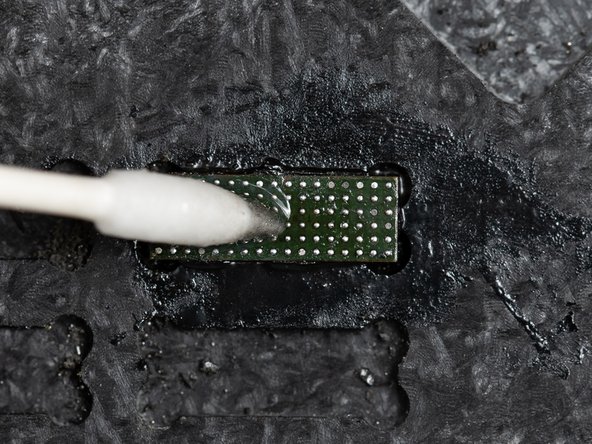
Clean the IC with some IPA using a cotton bud. This will ensure all of the underfill glue has been removed.
-
-
-
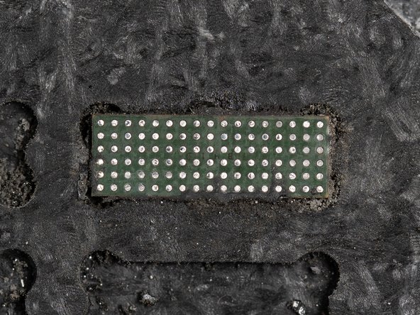
After cleaning you'll need to inspect your chip and see how shiny the joints are. If the solder joints aren't shiny it's because they are oxidized. If any of the joints are oxidized, you'll need to take a knife blade to each joint and scrape the surface to de-oxidize them.
-
If you've inspected your chip and all of your joints look shiny then well done! You can skip to Step 20.
-
The reason we're aiming for the joints to be de-oxidized is because the fresh solder paste we'll be applying won't merge with the joints as well if they are oxidized.
-
-
-
If you don't have a knife blade or would prefer to use a different method of de-oxidizing your joints then you can use this method instead.
-
Start by adding some flux to your chip. Apply enough that it can spread in an even layer across the entire chip.
-
We're adding flux so the solder wire we'll be using in the next step can melt easier. The flux also makes it easier for the solder wire to easily pass through the joints.
-
-
-
Set your soldering iron to 300°C and grab a small amount of low temperature solder wire.
-
Lower your soldering tip down to your chip along with your solder wire. Press the solder wire against the tip until the wire melts and creates a small ball.
-
Once the small ball has been created. Rub your solder tip across the board in a back and forth motion
-
-
-
If you've followed any of the last three steps of de-oxidizing your joints you'll need to clean your chip again.
-
Clean your chip with IPA and a cotton bud to remove any excess flux and underfill.
-
-
-
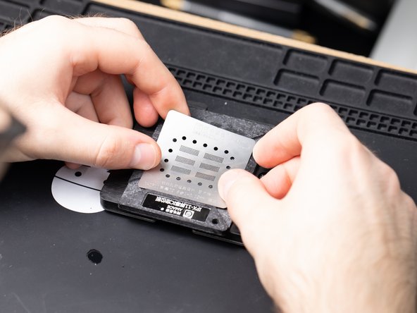
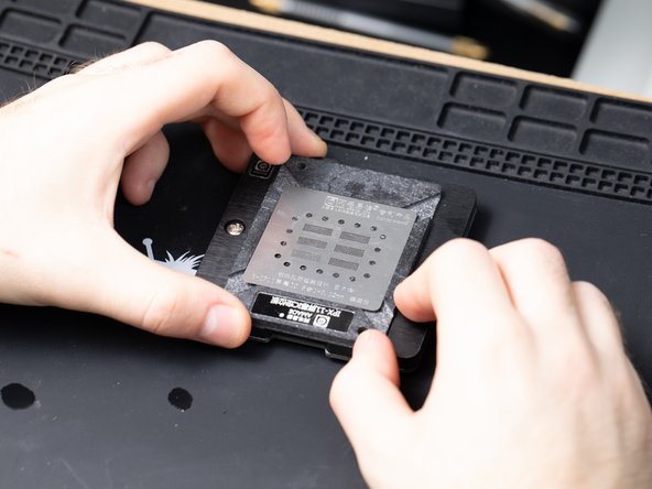
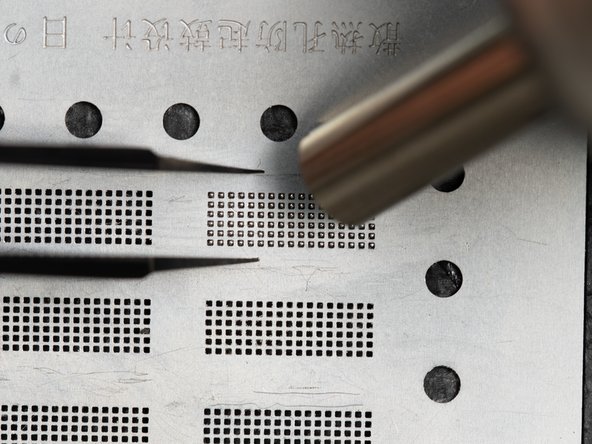
With your IC chip still resting on your platform, grab an iPhone 11 reballing stencil and wedge it on top of the platform.
-
Make sure your stencil is lined up with the chip.
-
-
-
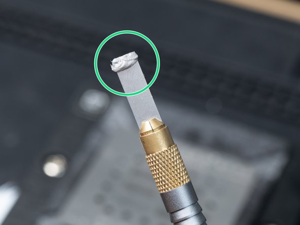
Apply a small amount of solder paste onto the end of your Qianli cleaner. We're using 138°C Solder Paste. Use one of the flat tip connections.
-
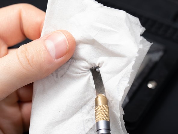
Next, dry the solder paste on a piece of tissue.
-
We are drying it out to make it easier to spread along the stencil. When it's wet and you boil it, it's harder to control the speed of reballing.
-
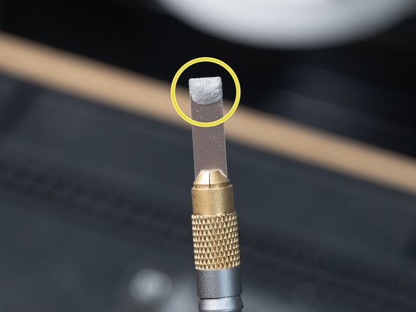
You can tell when the paste is dry enough when the paste is no longer shiny.
-
-
-
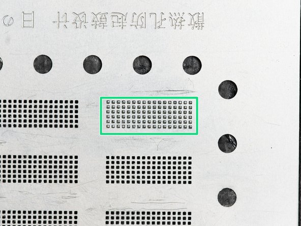
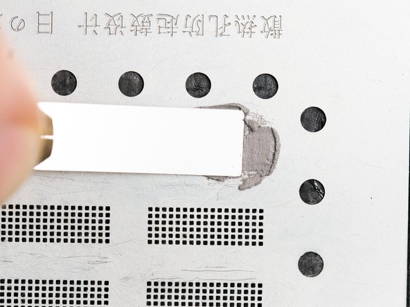
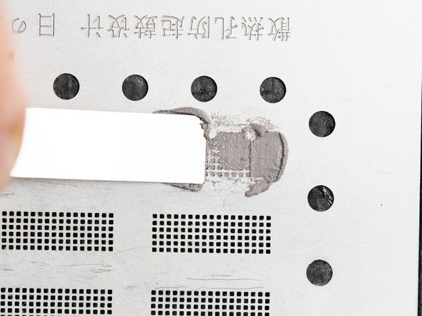
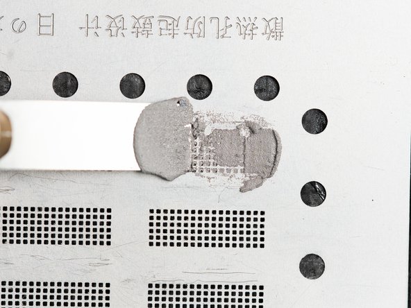
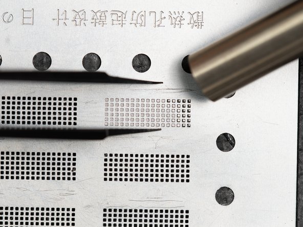
Rub the dried solder paste back and forth on top of the stencil to fill in all of the holes.
-
-
-
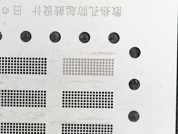
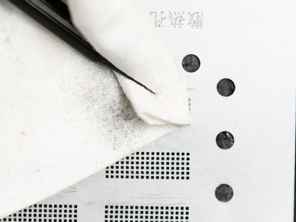
Check all of the holes are filled in with solder paste.
-
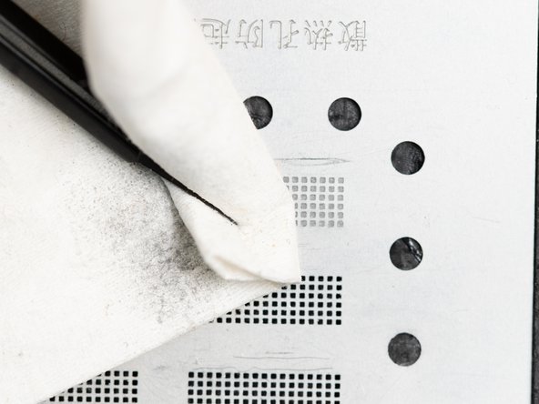
If all of the holes are filled in, clean the stencil with a cloth to get rid of any solder paste residue. Cleaning it also helps push the solder paste around the small holes in the stencil. This helps it sit in the right place, you may want to use firm pressure when doing this.
-
-
-
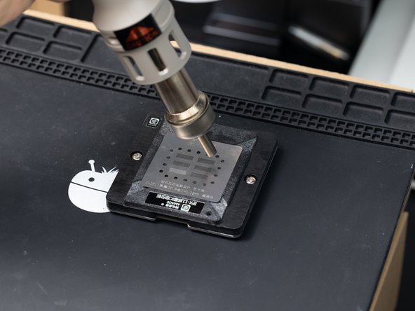
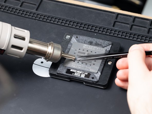
Set your hot air station. to 350°C with airflow set to 70. Heat around the solder paste and heat the stencil in circular motions.
-
Temperatures may vary depending on what solder rework station you're using.
-
-
-
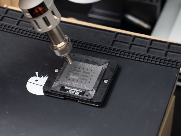
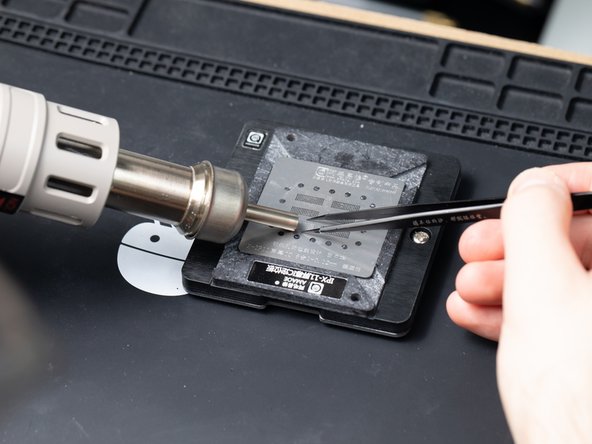
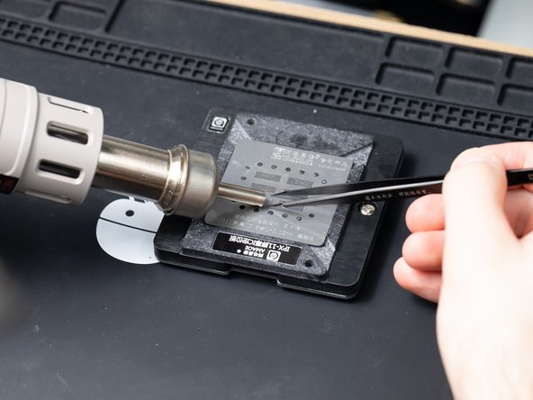
Move the hot air nozzle across the stencil the chip is on.
-
Hold the stencil with tweezers to stop it moving.
-
-
-
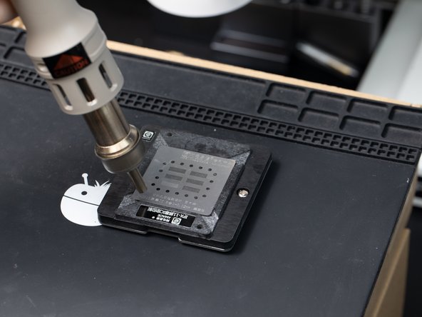
When you move the nozzle across the stencil you'll see the paste change colour which means the solder balls are forming.
-
-
-
Remove the stencil and add a drop of flux to the chip.
-
-
-
Heat the chip back and forth with hot air at 300°C with 70 airflow.
-
Heat for 10-15 seconds until you see the solder balls form.
-
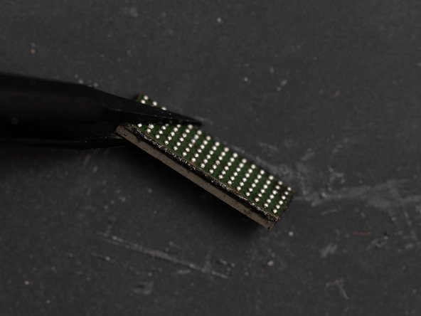
Once heated remove the chip from it's pocket.
-
If you're struggling to remove the chip you can use some IPA in one of the corners.
-
-
-
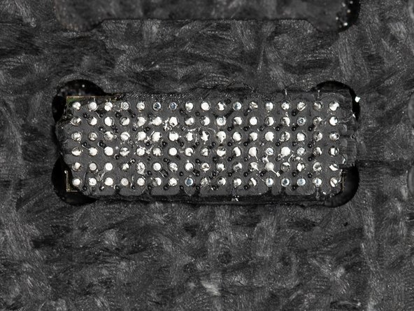
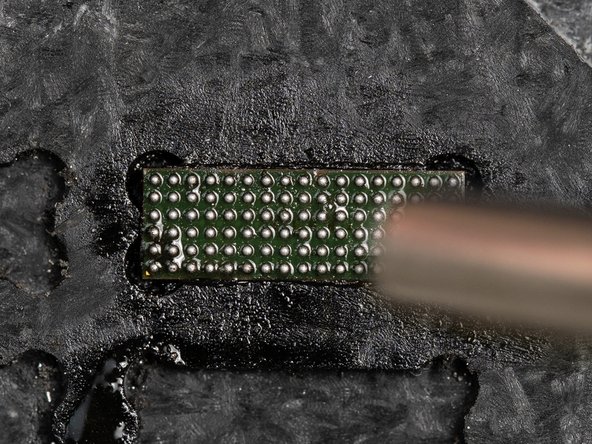
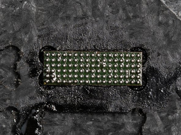
When inspecting the chip with the newly applied solder paste you're looking for all of the balls to be on the same level as eachother.
-
If they aren't all at the same level then the IC won't sit at the same level on the flex. This could create connection issues on the flex and make it harder for you to fit to the flex.
-
-
-
Next grab your iPhone 11 IP9 replacement screen.
-
-
-
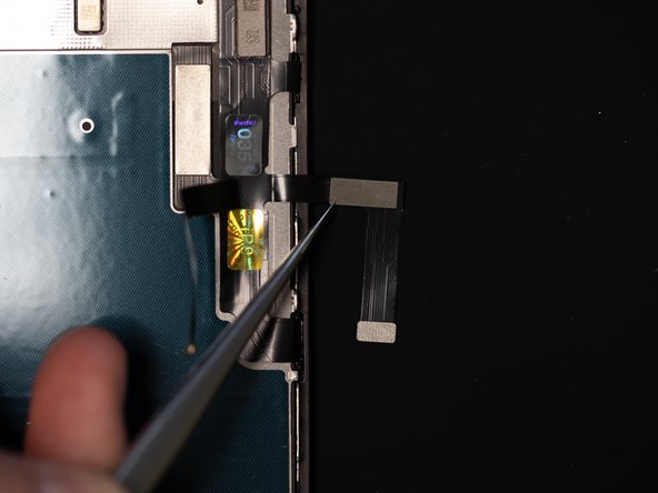
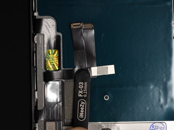
Unfold the section of the flex where you'll be applying the original IC chip.
-
-
-
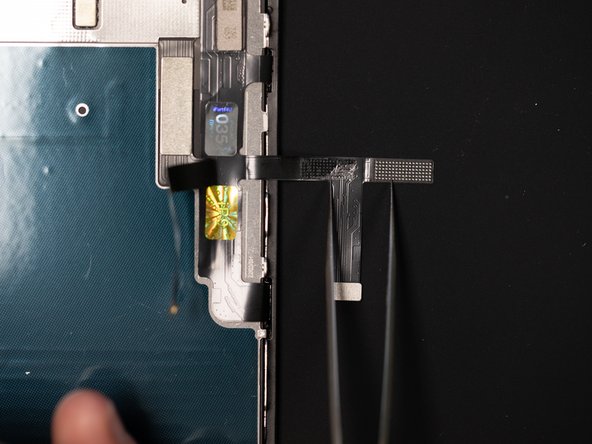
Fold the digitizer flex inwards.
-
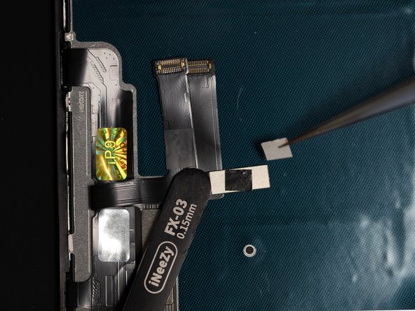
Cut a small square of Tesa Tape and using tweezers apply it to the back of the flex.
-
We're using 3mm x 25m Tesa tape, but you can use any Tesa tape that is double sided.
-
Once applied, peel off the the top layer of the tesa to reveal the sticky side.
-
-
-
Using the Tesa that you just applied, stick the flex to a reballing base or any flat surface that will withstand high temperatures & that the Tesa will stick to.
-
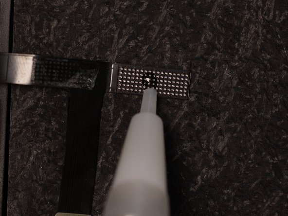
Apply some flux to the digitizer flex. This will help bond the IC to the flex.
-
Once the flux has been applied, spread the flux across all of the solder balls.
-
-
-
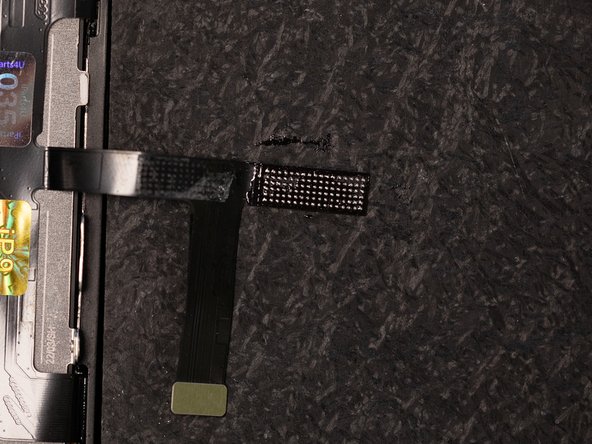
Put the IC back onto the flex.
-
Line it up with the balls.
-
-
-
Heat the IC with hot air in a back and forth motion.
-
Make sure to direct your airflow away from the screen as this could cause damage to the screen.
-
We're using 138°C solder paste so our temperature will be 280°C with the airflow set to 1%.
-
-
-
Heat the chip with the hot air nozzle and gently nudge the side of the IC with tweezers, you'll know when it's bonded when it bounces back into place.
-
Be careful not to press down on the IC or move the IC too far as it can cause a short under the IC.
-
-
-
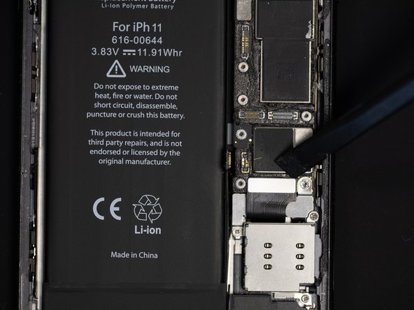
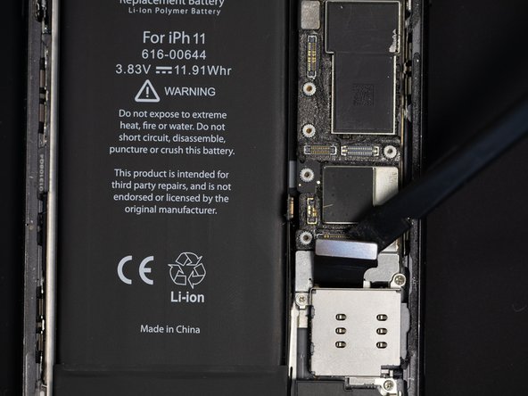
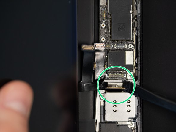
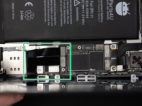
Using a spudger, disconnect the charging port flex.
-
-
-
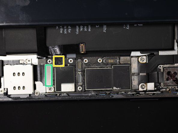
Slide the flex with the IC underneath the charging port flex.
-
-
-
Re-connect the charging port flex
-
Re-connect the battery flex.
-
Since the battery is already connected, you'll need to be careful when re-connecting the display & touch flex cables so as not to create a short. Please make sure you align them properly in order to avoid this.
-
We recommend fully discharging your battery before doing this to reduce the chances of a short.
-
-
-
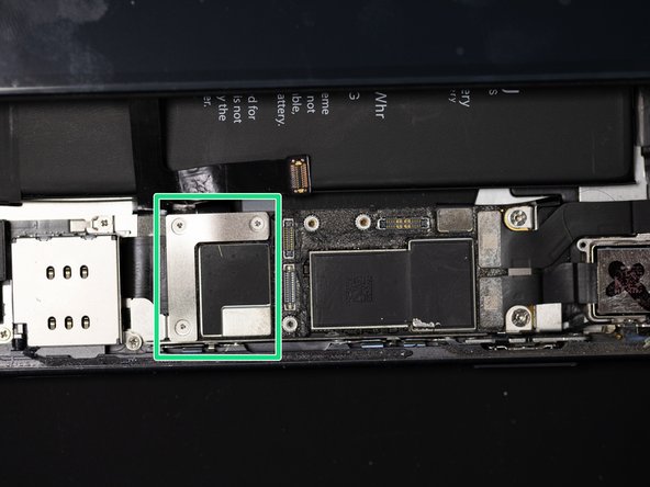
Screw the battery and charging port shield back down.
-
-
-
Connect the display and touch flexes.
-
Continue to fit the screen as normal from this point onwards.
-


Team
